Posts

Arduino DHT22 readings over serial
Image
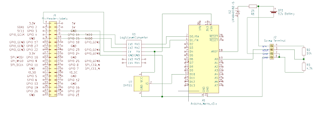
 Today I am going to add a DHT22 temperature humidity sensor to my existing battery voltage monitor project. Uploading and testing the code is done over USB cable, the HC-05 needs to be disconnected for this to work. The DHT22 is connected to +5v, gnd and Digital Pin 10, I only chose pin10 as it is convenient for my veroboard layout. The code for this is very simple : <code> #include "DHT.h" #define DHTPIN 2 // The pin that your DHT is connected to DHT dht(DHTPIN, DHT22); void setup() { dht.begin(); } void loop(){ float h = dht.readHumidity();     //stores humidity value in float variable h float t = dht.readTemperature();// temperature value } </code> Don't forget to import the "DHT sensor library" in library manager in the Arduino IDE.  We can then do whatever we need to with the values. I am going to send request them over serial via a HC-05 Bluetooth device from a Python script on a Raspberry Pi.  For testing  am using a laptop running ...

Laptop to Arduino Nano with HC-05 Bluetooth Module

Image
 After getting a serial connection to work between an Arduino Nano and Pi Zero in a previous project I purchased a HC-05 Bluetooth module so that the Pi can be removed from the enclosure, this should reduce the power requirement significantly resulting in increased battery life. Power requirements : Pi Zero, Arduino Nano 290mA Arduino Nano, HC-05 module Bluetooth Module 50mA The power reduction is huge but it is a bid of a mess when soldered onto veroboard. (I have ordered a few ESP32 for a future improved version.) The wiring diagram is very similar, just replace the Pi Zero with the HC-05 as below. You can ignore everything to the right of the Nano, it is not required for Bluetooth but i am using it to retrieve a battery level reading. When powered up the led on the HC-05 should flash rapidly indicating ready to connect. To test you can use the Android app "Serial Bluetooth Terminal". The default pairing code is "1234". I will be using Python to communicate with t...

Calculating Battery for Small Solar Project

Image
 Today is about planning the power side of a Raspberry Pi Zero W and Arduino Nano (Elegoo clone) greenhouse monitor. We need to calculate the battery and solar panel size so that it can run continually in the UK at least over the summer months. I have measured these figures to give us somewhere to start the calculations : Pi Zero W power draw low 90ma, med 118ma, high 193ma Arduino Nano Clone, running 1x ADC and serial 21ma  Full project usage 280ma :o this includes 12 to 5v switching voltage regulator  280ma is more than I was hoping for, maybe I will look in to reducing this by using a better voltage regulator (without an LED display etc). For now this is what I have to work with, lets add a small margin and call total current draw 300ma. We have around 8 hours a day sunlight hitting the panel so the rest of the time it will be running on battery. 24 - 8 = 16 hours absolute minimum battery = 16 * 300 = 4800mah = 4.8Ah  The cost of a 5Ah lead acid battery from RS Co...

Connecting Raspbery Pi to Arduino over serial pins / GPIO

Image
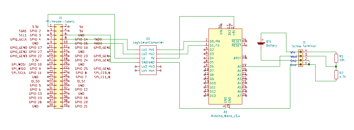
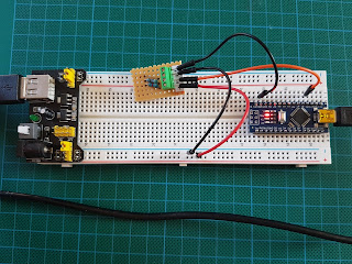
Warning ! the Raspberry Pi operates on 3.3v and the Arduino on 5v. Connecting the TX RX pins directly will damage the Pi!  Today we will be connecting a Raspberry Pi ZeroW to an Arduino Nano (Elegoo Clone) over serial interface to enable two way communication. We will test this using the previous voltage divider project .  To accomplish this we will need the following: Raspberry Pi Arduino Nano Logic level converter Breadboard + jumper wires Power supplies for each The wiring diagram is as follows :  I have set it out on a bread board as follows using the 3.3v and ground of the Arduino instead of a battery for the divider measurement.  The GPIO serial pins on the Pi need to be configured before we can use them. To do this connect / ssh into your Pi and run "sudo raspi-config". Select "3 Interface Options", then "P6 Serial Port". Would you like a login shell to be accessible over serial, select "No". Would you like serial port hardware to be enab...

Reading an Analogue Voltage with Arduino over USB Serial

Image
  The purpose of this mini project is to check that we can read the analogue signal from the voltage divider that was made previously . Transfer the value via serial connection and perform a calculation to check against measured values.   The circuit diagram is as follows :   To start, the voltage divider is connected to a 5v supply and analogue pin A0 of an Arduino Nano 3. In the Arduino IDE the code is as follows : const int pinA0 = A0;       // Analogue input pin that the battery is attached to int vBattery = 0;            // This will be our voltage reading. int incomingByte = 0;   // Holds the request void setup() {   Serial.begin(9600);                          // Start serial communications   Serial.println("Request reading by sending a request");   Serial.println("Pin A0, Battery = b"); } void loop()...

Raspbian Enable Remote Desktop

Image
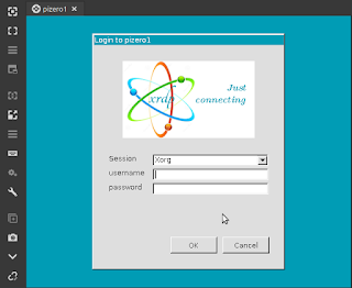
Remote desktop is not enabled by default on Raspbian for security reasons / people not changing the default password...naughty naughty. It does have RealVNC bulit in but it is not very good and requires RealVNC to be installed on your local machine as well, it is also not compatible with TightVnc etc. XRDP is a lot nicer in my opinion and seems to be a lot faster on a PiZero. To enable, SSH in to your Pi, and run "sudo apt install xrdp". You can now use the windows build in "Remote Desktop" application to connect to your Pi. If using linux i really like Remmina that supports VNC and XRDP. Log on using your credentials, default username is pi and default password is raspberry. Change your password from the terminal with "passwd" or if it is the first time you are accessing the desktop you can do it in the wizard.

Pi GPIO Connect an LED

Image
Connecting an LED to a GPIO and turning it on is probably one of the most simple things that we can use the Pi GPIO for. There is however a bit of thought that needs to go in to it so that we do not damage anything.   We will need the following : Pi with a GPIO LED 220ohm Resistor(red, red, black, black or any larger up to ~1k) Jumper wires Strictly speaking we should calculate the correct value for the resistor but 220ohm or above will be fine for both 3.3v RPi GPIO output and 5v if required. I have chosen GPIO21 (Pin40) as the output and the resistor is in series with the LED. The short leg of the LED goes towards ground.     Create a new python script "nano led.py" import RPi.GPIO as GPIO import time GPIO.setmode(GPIO.BCM) #Board is Physical pin 1-40, BCM is GPIO NN GPIO.setup(21, GPIO.OUT) #Sets GPIO 21 to output mode GPIO.output(21, GPIO.HIGH) #Sets GPIO 21 High +3.3v time.sleep(5) #Sleep / Wait for 5 seconds GPIO.output(21, GPIO.LOW) #Sets GPIO 21 Low 0v GPIO.cleanu...