Calibrate 3D Printer
Steps to Calibrate 3D Printer
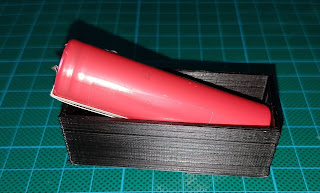
I have a very cheap Geetech I3 Pro B, it cost around £80 delivered in the UK. The slider bars are hollow, linear bearings are nylon, the frame is plywood and the heated plate is wonky but it is capable of some nice prints (after some modification, I will post about this when I have done a few more parts). It is however printing items smaller than they should be. I noticed this when printing a case to hold a 18650 battery and some circuit boards, they would not fit :/
Before attempting callibration please ensure that all belts are taught and nuts bolts and connections are secure. Pay special attention to your bed as mine had a lot of slack where it attached to the belt causing serious issues / circles and curves being uneven, dimensions being short on that axis being the most obvious issue.
This can be resolved by calibrating the printer stepper motors but we may as well calibrate all of them to get the best prints possible. I will do it in the following order. Please note that not all printers will save the calibration between reboots even if told to save them to EEPROM, mine included. We can work around this limitation by using the pre print gcode before each print.
- Temperature PID Hot End
- Temperature PID Bed
- Extruder - The length of cold material pushed into the hot end
- X Axis
- Y Axis
- Z Axis
- Ensure values are used for every print.
1. To PID calibrate the hot end.
Open a terminal connection to the printer, I am using OctoPrint.
M503 - to view current settings.
M303 E0 S200 - Starts PID calibration, give it 10 minutes. S = Temp E = Extruder number.
Once complete it should display something like :
Recv:  Classic PID
Recv:  Kp: 22.09
Recv:  Ki: 1.34
Recv:  Kd: 91.21
Recv: PID Autotune finished! Put the last Kp, Ki and Kd constants from above into Configuration.h
To save the values enter your P I and D values into the following command and send.
M301 P22.09 I1.34 D91.21
M500 - saves the value to EEPROM
To check send M503, it should display the new values.
2. To PID Calibrate the bed.
M303 E-1 S50
Recv:  bias: 55 d: 55 min: 49.75 max: 50.23
Recv:  Ku: 295.49 Tu: 10.49
Recv:  Classic PID
Recv:  Kp: 177.29
Recv:  Ki: 33.82
Recv:  Kd: 232.39
M304 P177.29 I33.82 D232.39 - substitute your values.
M500
3. Extruder
To View Current Stepper / Movement Settings M503
Send: M503
Recv: echo:Steps per unit:
Recv: echo:  M92 X78.74 Y78.74 Z2560.00 E105.00
Recv: echo:Maximum feedrates (mm/s):
Recv: echo:  M203 X400.00 Y400.00 Z2.00 E45.00
Recv: echo:Maximum Acceleration (mm/s2):
Recv: echo:  M201 X1400 Y1400 Z100 E80000
Recv: echo:Acceleration: S=acceleration, T=retract acceleration
Recv: echo:  M204 S1400.00 T5000.00
Recv: echo:Advanced variables: S=Min feedrate (mm/s), T=Min travel feedrate (mm/s), B=minimum segment time (ms), X=maximum XY jerk (mm/s),  Z=maximum Z jerk (mm/s),  E=maximum E jerk (mm/s)
Recv: echo:  M205 S0.00 T0.00 B20000 X13.50 Z0.30 E5.00
Recv: echo:Home offset (mm):
Recv: echo:  M206 X0.00 Y0.00 Z0.00
Recv: echo:PID settings:
Recv: echo:   M301 P19.86 I1.00 D98.93
Recv: ok
The part we are interested in is :
M92 X78.74 Y78.74 Z2560.00 E105.00The X, Y, Z values represent the stepper motor steps per mm. E is mm of cold filament pushed to the hot end.
Ensure that the hot end is up to temperature and the extruder is at least 20 mm away from the bed.
Measure 50mm from the extruder along the cold filament and mark a point on the filament with a marker or post it note etc. measure the exact distance and note it down as value A.
Extrude 10mm of filament and measure the distance again note it as value B.
The actual distance extruded is A - B. If this value = 10 then the extruder calibration is ok. If not take a few more readings and calculate the average.
50.32 - 40.08 = 10.24
49.99 - 39.05 = 10.94
50.23 - 39.56 = 10.67
(10.24+10.94+10.67) / 3 = 10.61
On average the printer is over extruding slightly.
To calculate the calibration value we use :
New value = Current E Value * 10 / Average Extruded Value
New Value = 105 * 10 / 10.61
New Value = 98.96
To send this value to the printer send command :
M92 E98.96
Where E is followed by your value. Save the value with M500.
4. X Axis
To View Current Stepper / Movement Settings M503
Move x 100mm
Start 10mm
End 110mm
Actual 100mm
I do not require any adjustment on this axis but the calculation is the same as the extruder calculation :
New value = Current X Value * 100 / Actual Moved
New Value = 78.74 * 100 / 100
New Value = 78.74
M92 X78.74
Where X is followed by your value. Save the value with M500.
5. Y Axis
The same as the X axis....
Move Y 100mm
Start 10 mm
End 108 mm
Actual 98 mm
New value = Current Y Value * 100 / Actual Moved
New Value = 78.74 * 100 / 98
New Value = 80.35
6. Z Axis
The same as the X axis....
Move z 100mm
Start 10mm
End 110mm
Actual 100
Again mine was spot on from what I could measure.
New Value = 2560 * 100 / 100
New Value = 2560
M92
7. Ensure Values Are Used
As my printer is very cheap it does not retain settings after a power off and reloads with defaults. To ensure that our calibrated settings are used we can include them with every print from the slicer or control software.
If you are using OctoPrint to control the printer go to settings then GCODE Scripts. Enter your calibration values as shown below.
M304 P177.29 I33.82 D232.39
M301 P22.09 I1.34 D91.21
M92 X78.74 Y80.35 Z2560 E98.96
You can do the same in Cura under manage printer, machine settings, configuration, Start GCODE.
I recommend you print a calibration cube to verify your settings, good luck !


Comments
Post a Comment