Making a Voltage Divider For a 12V Solar System
I would like to measure the charge state of a 12V solar system. Unfortunately i have let the smoke out of a Pi Zero previously using an ADC that cost more than the Pi, whoopsy. A separate ADC is required as the Pi does not have any analogue inputs.
This time I have decided to design my own using a voltage divider circuit to scale down the reading to a level that can be read by a Arduino Nano that has a maximum 5V input.
First thing first, calculations.
The formula for a voltage divider is:
Vout = (R2 / R1 + R2) x Vin
Our Vin will be the battery maximum voltage, when charging this should be around 14.7V but i have seen the cheap charge controller spike to 15V. Just to be safe i am going to say 16V.
Vout needs to be less than 5V.
I have a box of resistors so i am going to use common values for R1 and R2. I know that if R1 and R2 are the same the Output will be half the input across each resistor so i settled on R1 = 10 and R2 =4.7.
Vout = (4.7/10+4.7)x16
Vout = (4.7/14.7)x16
Vout = 0.3197*16
Vout = 5.1152V
This should be fine for our needs as i have been cautious selecting a higher max input voltage. If we calculate for 15V input we get 4.7995V that is within spec for the analogue input for the ADC.
Next we need to check the current in the circuit, we want it as small as possible to prevent the battery just heating (or melting) the resistors and draining itself.
I = V/R
I= 16/14.7
I= 1.08A
1A may melt these resistors and waste a lot of power if they survive. If we increase the value to k ohms (16/14700) we get a much more acceptable 0.001 A or 1mA.
Now for the fun part... The circuit diagram, should look like this.
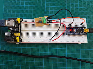
Lets replicate that with the hardware and compare our Vin and Vout to the calculations.
Typically overcast day in Wales, the panel is only charging at 13.3V, our Vout measures = 4.25V. If we check this with our calculations it is pretty much spot on, i am surprised :)0.3197 * 13.3 = 4.25
Vin = 12.7, Measured Vout = 4.03
0.3197 * 12.7 = 4.06
We have a small discrepancy between our measurements and calculations of 0.03V Vout with a difference of 0.6V on the input. I think additional measurements are required but not bad for a first attempt.
Lets tidy this circuit up a bit so that it can be used in a future project.
Im looking forward to using this with an Arduino soon :)


Comments
Post a Comment